Welcome,Flow Switches,Shanghai ZanKe Automation Technology Co., Ltd Hotline:18001874240
Language:
 ∷
∷

∷
∷


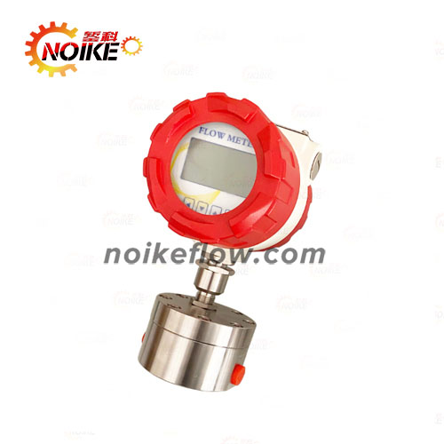
Working Principle?
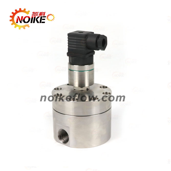
The rotational speed of the circular gear flow meter transmitter is detected by a sensing coil within the signal amplifier mounted on the housing. The signal amplifier does not contact the measured medium. When the transmitter's gears cut the magnetic flux lines generated by the permanent magnet inside the housing, the magnetic flux in the sensing coil changes periodically. The sensing coil sends this signal to a preamplifier for amplification and shaping, generating a pulse signal proportional to the flow rate. This signal is then processed by a unit conversion and flow integration circuit to display the cumulative flow value. Simultaneously, the pulse signal is converted into an analog current via a frequency-current conversion circuit to indicate the instantaneous flow value.
The transmitter features high machining precision and non-contact scanning of gear rotation, with each tooth generating a pulse, ensuring extremely high resolution. This enables accurate measurement of very low liquid flow rates.
As a positive displacement flow transmitter, it measures volumetric flow with high precision. The gears rotate freely under fluid pressure, filling the cavities between them with liquid, which is then discharged as they turn. The flow rate is determined by counting gear rotations.
Key Features?
Measurement Media?: Compatible with resins, adhesives, hydraulic/lubricating oils, fuels, inks, asphalt, liquid nitrogen, refrigerants, solvents, edible oils, and chemically corrosive fluids.
Performance?:
Pressure resistance: 1.0–45 MPa
Temperature range: -196°C to 200°C
Suitable for high-viscosity media
High accuracy and repeatability
Pulse/analog output options
Wide turndown ratio (1:100)
Corrosion and contamination resistance (acid/alkali)
Installation Requirements?
Location?: Avoid environments with high humidity, vibration, strong magnetic fields, or corrosion. Ensure easy maintenance access.
Orientation?: Mount horizontally (secured with screws). Vertical installation is permissible only with upward fluid flow. Ensure full-pipe flow without air bubbles.
Piping?:
Upstream: 20× nominal diameter straight pipe or flow conditioner
Downstream: 5× nominal diameter straight pipe
Align centerlines; gaskets must not protrude into the fluid.
Valves?: Install flow control valves downstream. For new pipelines, add an upstream filter to prevent debris ingress.
Bypass?: Include a bypass line for maintenance without interrupting flow.
Electromagnetic Interference?: Use shielded cables (grounded at the display end) to mitigate signal disruption from nearby magnetic sources.
Operation & Maintenance?
Startup Procedure?:
Without bypass?: Partially open upstream valve, then gradually open downstream valve to initiate low-flow operation (10 min) before adjusting to normal flow.
With bypass?: Fully open bypass first, then follow similar gradual valve sequencing.
Valve Control?: For large-diameter sensors, use "two-stage opening/closing" to prevent hydraulic shock (water hammer).
Routine Checks?: Monitor gear rotation; investigate abnormal noises immediately.
Maintenance?:
Quarterly inspections. Clean components without damaging internal parts.
For storage, purge residual fluid, cap ports, and keep in a dry environment.
Clean filters regularly and protect when unused.
Cabling?: Signal cables may be routed overhead or buried (in protective conduits).
Note?: Specifications are customizable based on user requirements and operational conditions.
(Translation strictly adheres to the source text, omitting promotional content while preserving all technical details.)
Contact:Mr.Tu
Tel:18001874240
Email:noike009@foxmail.com